Discussions of space data centers often produce two opposing claims: "space is cold, so cooling is easy" and "heat has nowhere to go in a vacuum, so a data center is impossible." Neither is correct. Although a vacuum rules out convection to the surrounding air, heat can still escape as infrared radiation. A facility that already needs thousands of square meters of solar panels may also be able to accommodate radiators (heat-rejection panels) covering roughly a thousand square meters—at least in terms of area. This article considers a 1 MW-scale solar-powered data center operating at roughly Earth's distance from the Sun and estimates the radiator area it would require.
1. Radiator area and mass on the ISS
We begin with a large space facility that already exists: the International Space Station (ISS). NASA documents put the area of its solar arrays at about 2,247 m²[1]. We will use that figure as a reference point throughout this article.
The ISS now carries six iROSA arrays in addition to its eight original main arrays, so 2,247 m² is not the total solar-array area of the current configuration. Here, the figure serves only as a point of comparison for the scale of its external structures.
The US segment's main Heat Rejection System (HRS) can reject up to 70 kW. It consists of six radiator panels (ORUs), each measuring 23.3 m × 3.4 m, with a combined projected area of about 475 m² based on their external dimensions. Four additional radiators cool the photovoltaic power equipment (PVRs, each 3.12 m × 13.6 m and rated for up to 14 kW). Together, these radiators have a maximum heat-rejection capacity of about 126 kW and a projected area of roughly 645 m²[2]. A 2025 NASA document gives a total radiating surface area of roughly 1,300 m², approximately twice that 645 m² projected area[5].
The point is not to determine which area is larger. It is that radiators spanning several hundred square meters already operate in space alongside solar arrays as major external structures in their own right. On the ISS—a real, operational example—the heat-rejection hardware is not orders of magnitude larger than the power-generation hardware.
Deployed area alone, of course, tells us nothing about how difficult the equipment is to build. Based on NASA's nominal figures, the six HRS units and four PVRs have a combined mass of about 9.7 t—and that excludes the pumps, tanks, rotary joints, heat exchangers, and external plumbing. The ISS demonstrates that heat can be rejected in space, but it also shows how difficult it is to make large cooling structures lightweight[2]. The solar arrays are hardly light, however: NASA's nominal figures put the combined mass of the eight original Solar Array Wings at at least 8.7 t. In terms of mass, too, the radiator assemblies and solar arrays are of the same order of magnitude[3].
NASA's STS-119 press kit gives the mass of each original Solar Array Wing (SAW) as more than 2,400 lb (about 1.09 t). Across all eight wings, that is at least \(2{,}400\times8\ \mathrm{lb}\simeq8.7\ \mathrm{t}\), or at least about 3.9 kg/m² over the 2,247 m² array area. This figure excludes the supporting truss, rotary joints, power-conversion equipment, and six additional iROSA arrays, so the current solar-power system is heavier still.
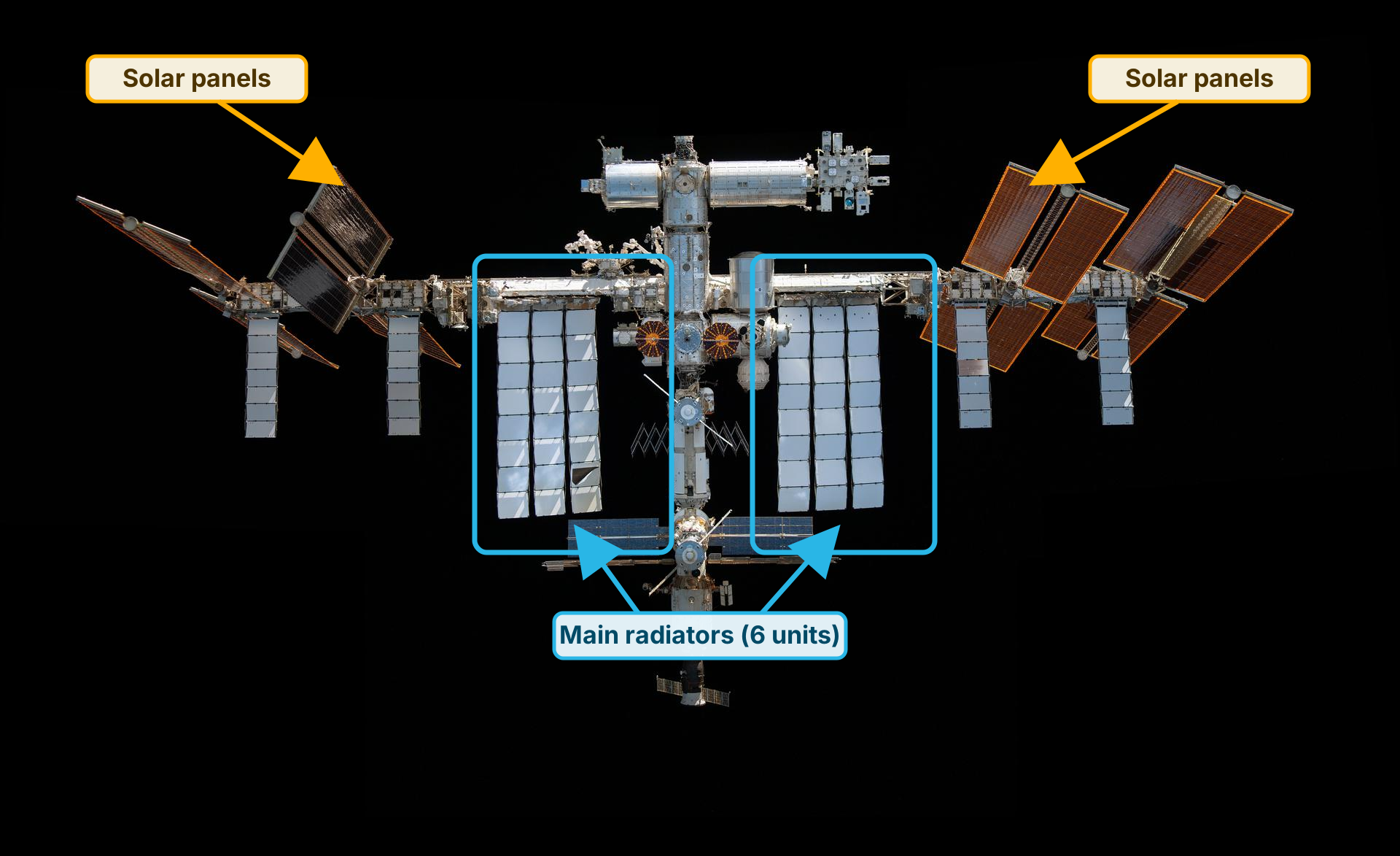
Figure 1: Solar panels and main radiators of the ISS
The orange arrows mark the solar panels, and the blue outlines mark the six HRS radiators. The 645 m² projected area cited in the text also includes the four PVRs, which are not outlined here. The photograph is NASA ID "jsc2021e064215_alt," taken by Thomas Pesquet / ESA on November 8, 2021[6]. The figure is used for informational purposes in accordance with NASA's media usage guidelines[7].
2. Thermal radiation can reject heat even in a vacuum
Heat is transferred in three ways: conduction through matter, convection through a fluid, and radiation in the form of electromagnetic waves. Space provides no ambient air for convection, but circulating coolant and conduction through pipes and panels can still carry heat within the facility. The radiators then release it into space as infrared radiation.
The rate at which a radiator facing only deep space can reject heat increases with both its area and its temperature. Because radiated power rises with the fourth power of absolute temperature, operating temperature has a major effect on the required area. A rigorous calculation must also account for the surface's infrared emissivity and for radiation received from its surroundings.
From the Stefan–Boltzmann law, the net heat rejection of a radiator facing only deep space is
\[
P
=
\varepsilon \sigma A
\left(T_\mathrm{radiator}^{4}-T_\mathrm{sink}^{4}\right)
\]
where \(A\) is the infrared-emitting surface area, \(\varepsilon\) is the infrared emissivity, and \(\sigma\) is the Stefan–Boltzmann constant. For radiator temperatures around 0–100 ℃, the background radiation from deep space is negligible, so the rejected power is nearly proportional to \(T_\mathrm{radiator}^4\).
To develop some intuition, consider an object with no internal heat source at Earth's distance from the Sun. At that distance, a surface facing the Sun receives 1,361.6 W of solar energy per square meter[8]. The object absorbs sunlight and warms until it reaches a temperature at which the absorbed energy equals the infrared energy it radiates away.
If only solar absorption and infrared emission balance, then
\[
\alpha S A_\mathrm{projected}
=
\varepsilon \sigma A_\mathrm{emitting}T^4
\]
holds, where \(A_\mathrm{projected}\) is the projected area as seen from the Sun and \(A_\mathrm{emitting}\) is the infrared-emitting surface area.
For a perfect infrared emitter, geometry and solar reflectivity alone can shift the equilibrium temperature substantially, as the table below shows. The first two cases absorb all incident sunlight.
Object
Ratio of projected to emitting area
Equilibrium temperature
A thin flat plate facing the Sun, radiating from both sides
1 : 2
about 58 ℃
A sphere with a uniform surface temperature
1 : 4
about 5 ℃
A sphere with the same Bond albedo as Earth, 0.30
absorptivity 0.70, 1 : 4
about −18.5 ℃
The final value is Earth's effective radiating temperature when viewed from space as a sphere of uniform temperature, not its actual surface temperature. Remarkably, even at the same distance from the Sun, differences in sunlight-collecting area, infrared-emitting area, and reflectivity can shift the equilibrium temperature by more than 70 ℃. Temperature is determined not by "how cold space is," but by how much energy an object receives and how much it radiates away.
In low Earth orbit, a radiator also receives radiation from the Sun, Earth, and nearby structures, all of which must be included in its heat balance[9].
3. Absorbed solar energy must ultimately be radiated away
A solar panel reflects some of the sunlight that strikes it and absorbs the rest. The portion of the absorbed energy converted into electricity travels through wiring to the computers, where nearly all of it ultimately becomes heat in CPUs, GPUs, memory, and other components. A GPU does not create energy when it computes; energy that arrived as sunlight simply becomes heat, with electricity as an intermediate form. For a given power draw, the same amount of heat is produced whether the electricity powers useful computation or simply passes through a resistor.
At steady state, the energy absorbed by a solar panel is divided between electricity delivered to the load and heat dissipated by the panel itself.
This heat balance can be written as
\[
P_\mathrm{solar,absorbed}
=
P_\mathrm{electric,out}
+P_\mathrm{panel,thermal}
\]
What happens when no power is extracted? The panel continues to receive sunlight. Energy that would otherwise leave as electricity must instead be radiated by the panel, causing it to settle at a higher temperature. NASA thermal analyses describe precisely this behavior: during normal operation, some absorbed energy leaves as electricity; with no power extraction, all of it must be reradiated, and the panel runs hotter[10]. Solar panels therefore require their own thermal design even when they deliver no power, and excessive temperatures reduce both performance and service life[11].
It follows that when computation stops and the solar panels supply no power, the load on the data center's radiators falls—but the panels themselves must dissipate correspondingly more heat. Conversely, if the computers continuously receive 1 MW, about 1 MW of the energy absorbed by the panels leaves as electricity, becomes roughly 1 MW of heat in the computing equipment, and is rejected through the data center's radiators. Solar energy absorbed by the facility must ultimately be radiated back into space somewhere, whether or not it passes through the power system and computing hardware first.
In the calculations below, we assume that the facility draws 1 MW continuously and rejects an average of about 1 MW through its data-center radiators. If the IT equipment alone—GPUs and similar hardware—draws 1 MW, then both generation and heat rejection must exceed 1 MW to cover power conversion, communications, pumps, attitude control, and other subsystems.
4. A continuous 1 MW load requires thousands of square meters of solar panels
According to NASA's 2026 review of spacecraft power systems, today's space-grade multijunction solar cells have nominal efficiencies of about 30%, with the best reaching roughly 34%[11]. We optimistically assume that the panel's entire surface is covered with cells operating at 30% efficiency. Multiplying the solar irradiance at Earth's orbital distance, 1,361.6 W/m², by 30% yields about 408 W per square meter in sunlight[8].
The power output of a sunlit solar panel is
\[
P_\mathrm{PV}
=
\eta_\mathrm{PV} S A_\mathrm{PV}
\]
Even if the panel always faces the Sun head-on and we ignore degradation, gaps between cells, wiring, and power-conversion losses entirely, producing 1 MW requires \(1{,}000{,}000/(1361.6\times0.30)\simeq2{,}448\ \mathrm{m^2}\).
In low Earth orbit, moreover, the facility passes through Earth's shadow once per orbit. During the sunlit portion, it must both run the load and store enough energy for the eclipse. Suppose that 55 minutes of a 90-minute orbit are sunlit and 35 minutes are in eclipse, and that the storage system has a round-trip efficiency of 90%. While in sunlight, the facility must then generate about 1.71 times its continuous load, increasing the solar-panel area needed for a continuous 1 MW load to about 4,179 m².
\[
1+\frac{35}{0.90\times55}
\simeq
1.707
\]
In this example, storage losses add an orbit-averaged heat load of about 43 kW, but we leave this out of the radiator-area calculations below to keep the comparison simple.
Conditions for powering a 1 MW continuous load
Solar panel area
Continuous sunlight, 30% conversion efficiency, no other losses
about 2,448 m²
55 min sunlight / 35 min eclipse, 90% round-trip storage efficiency
about 4,179 m²
In practice, the design must account for cell packing density, temperature, aging, distribution losses, pointing errors, safety margins, and other factors, making 2,448 m² a lower bound. We use the range of 2,448–4,179 m² below as a benchmark for the scale of the power-generation equipment.
5. Coolant temperature and radiator surface temperature are not the same
For the ISS HRS estimates below, we use an effective radiating temperature of about −0.8 ℃, derived from NASA's design conditions at maximum capacity. This allows the thermal-radiation calculation and the HRS's nominal maximum capacity to be compared on the same basis.
Under NASA's design conditions at maximum capacity, ammonia enters the radiator at about 10.2 ℃ and leaves at about −5.5 ℃, for an average of about 2.4 ℃. The average panel surface temperature is about 0.8 ℃, the fin efficiency is 88%, and the equivalent sink temperature is about −27.8 ℃. Under these conditions, each ORU rejects about 11.68 kW, giving the six-unit HRS a nominal maximum capacity of about 70 kW[4]. The −40 ℃ figure in another NASA document is a target outlet temperature used to control radiator orientation; it is neither the outlet temperature at maximum capacity nor the temperature of the radiator surface as a whole. Similarly, the roughly 2.8 ℃ figure is the supply temperature obtained by mixing the cold radiator outlet flow with a warm bypass flow before sending it to the heat exchangers[2].
NVIDIA's materials confirm that Vera Rubin-generation MGX racks can accept coolant at inlet temperatures of around 45 ℃[14]. The coolant absorbs heat in the racks, warms up, is cooled in the radiators, and returns. Because transferring heat from the coolant to the radiating surface requires a temperature difference, the coolant temperatures at the rack inlet, rack outlet, and inside the radiator—and the temperature of the radiator surface itself—are all different.
Whether a 40 ℃ radiating surface is achievable depends on the coolant return temperature and the overall thermal resistance between the coolant and the surface. The 60 ℃ case is a sensitivity test based on the assumption that an even higher return temperature can be achieved. Thus, the 40–60 ℃ range used here is not a product specification; it is a set of assumed conditions for examining how the required area varies with temperature. An actual design would need to specify coolant supply and return temperatures, flow rates, heat-exchanger performance, and the thermal resistance between the flow channels and the radiating surface.
6. How much radiator area is needed?
Here, projected area means the frontal area of a thin-plate radiator that radiates from both faces. Consider first an idealized surface with an infrared emissivity of 0.90, a uniform temperature, and no external heat input. Each square meter of radiating surface rejects 491 W at 40 ℃ and 629 W at 60 ℃. These figures ignore both environmental heat input and portions of the hardware that do not radiate, however, so they do not directly determine the area required by a real system.
In low Earth orbit, a radiator is exposed to direct sunlight, infrared radiation from Earth, sunlight reflected by Earth and its clouds, and radiation from nearby structures. The NASA Ames Research Center design standard specifies a direct solar flux of 1,322–1,414 W/m² for Earth-orbit designs and a global annual-average terrestrial infrared flux of 234 ± 7 W/m². The albedo contribution from reflected sunlight varies with the orbit and cloud cover[12].
AZ-93, a white thermal-control paint used on spacecraft, has a nominal solar absorptivity of 0.15 and an infrared emissivity of 0.91[13]. Because sunlight and thermal infrared occupy different wavelength bands, a surface can absorb relatively little sunlight while readily emitting infrared radiation. Even so, when facing the Sun directly, such a surface would absorb about 204 W/m²—a substantial amount compared with the 491 W/m² emitted by an ideal surface at 40 ℃. It is therefore important to keep the radiators edge-on to the Sun and position them to minimize heat received from Earth and other warm surfaces.
Real radiator surfaces also vary in temperature and include components that contribute little to heat rejection, such as supports, deployment mechanisms, and plumbing. In the calculations below, we therefore represent the nonuniform temperature distribution by a single equivalent temperature that produces the same total radiated power, while also accounting for the fraction of the area that actively radiates.
The effective radiating temperature is defined by
\[
T_\mathrm{eff}^4
=
\frac{1}{A_\mathrm{active}}
\int_{A_\mathrm{active}}T(\mathbf{x})^4\,\mathrm{d}A
\]
where \(A_\mathrm{active}\) is the actual radiating area and \(T(\mathbf{x})\) is the local surface temperature. If the external heat input is denoted by \(q_\mathrm{env}\), the net heat-rejection rate per square meter of geometric area on one face is
\[
q_\mathrm{net}
=
f_A\varepsilon\sigma T_\mathrm{eff}^4
-q_\mathrm{env}
\]
In practice \(q_\mathrm{env}\) differs between the front and back faces, so each face's rejection is computed separately and the two are summed.
To compare the required areas, we assume that 80% of the surface actively radiates, as in the ISS HRS, and examine two cases: no environmental heat input, and net environmental absorption of 148 W per square meter of geometric area on each face. The latter applies the environmental heat load derived from the ISS HRS equivalent sink temperature to surfaces at 40 ℃ and 60 ℃. This is not an analysis of a specific space-data-center design; holding the environment constant simply allows the temperatures to be compared directly.
For the ISS HRS, the table includes both an estimate calculated from NASA's design conditions using the thermal-radiation equation and a value derived from the system's nominal maximum capacity.
The 129.8 m² radiating surface of one ISS HRS ORU is about 82% of the 158.4 m² two-sided area calculated from its external dimensions, so an effective area fraction of 80% is broadly consistent with the actual hardware[4]. Given an average ammonia temperature of \(T_\mathrm{NH3}=275.5\ \mathrm{K}\), fin efficiency of \(\eta_\mathrm{fin}=0.88\), and equivalent sink temperature of \(T_\mathrm{sink}=245.4\ \mathrm{K}\), the effective radiating temperature that produces the same net heat rejection is
\[
T_\mathrm{eff}
=
\left[
T_\mathrm{sink}^4
+
\eta_\mathrm{fin}
\left(
T_\mathrm{NH3}^4-T_\mathrm{sink}^4
\right)
\right]^{1/4}
\simeq
272.4\ \mathrm{K}
\quad
\left(-0.8\ ^\circ\mathrm{C}\right)
\]
Because fin efficiency is incorporated into this effective radiating temperature, it differs from the average panel surface temperature of roughly 0.8 ℃ reported in the NASA document. With an effective area fraction of 80% and an infrared emissivity of 0.90, the equivalent sink represents the following environmental heat load per square meter of geometric area on each face:
\[
q_\mathrm{env}
=
0.80\times0.90\times\sigma\times(245.4\ \mathrm{K})^4
\simeq
148\ \mathrm{W/m^2}
\]
Across both faces, the net heat rejection per unit of projected area is about 153 W/m², so rejecting 1 MW requires about 6,520 m² of projected area.
For comparison, dividing the HRS's nominal maximum capacity of 70 kW by its projected area of roughly 475 m² gives about 147 W/m²—within about 4% of the simplified calculation. Scaling that value proportionally to 1 MW yields about 6,790 m². At an average ammonia temperature of 2.4 ℃, two-sided radiation would reject about 588 W/m² if the reduction in active area, fin efficiency, and environmental heat input were all ignored. The nominal figure is only about 25% of this ideal value. Most of the 75% difference is explained by the known conditions: an 80% effective area fraction, 88% fin efficiency, and an equivalent sink temperature of −27.8 ℃.
Condition
Effective radiating temperature
Effective area fraction
Environmental heat input (per face)
Net rejection per unit projected area
Projected area required to reject 1 MW
ISS HRS design conditions applied to the equation two-sided radiation
about −0.8 ℃
80%
about 148 W/m²
about 153 W/m²
about 6,520 m²
ISS HRS nominal maximum capacity 70 kW ÷ about 475 m²
—
—
—
about 147 W/m²
about 6,790 m²
No environmental heat input, two-sided radiation
40 ℃
80%
0 W/m²
about 786 W/m²
about 1,274 m²
Same environmental heat input as the ISS, two-sided radiation
40 ℃
80%
about 148 W/m²
about 489 W/m²
about 2,044 m²
Same environmental heat input as the ISS, two-sided radiation
60 ℃
80%
about 148 W/m²
about 710 W/m²
about 1,409 m²
Scaling the ISS HRS's nominal maximum capacity to 1 MW gives an area of about 6,790 m², whereas the estimates for 40–60 ℃ under the same environmental heat input are about 1,400–2,050 m². Even with identical environmental conditions, raising the effective radiating temperature above the HRS value of roughly −0.8 ℃ reduces the required area severalfold. The point is not that any particular area represents a threshold for feasibility. Rather, operating temperature largely determines radiator size, and at plausible temperatures, radiators need not be orders of magnitude larger than the power-generation equipment.
The ability to radiate from both faces also helps keep the required area down. If only one face is usable, the projected area nearly doubles—to about 4,090 m² in the example with a temperature of 40 ℃, an effective area fraction of 80%, and environmental heat input of 148 W/m² per face. Whether both faces have an unobstructed view of cold space is therefore another important design consideration.
These figures are not design values for any specific orbit. Actual hardware requires analysis of the orbit, attitude, view factors for each face, degradation of surface properties, worst-case hot conditions, and allowances for failures. Even so, the estimates show that the laws of physics do not require an extraordinary amount of radiator area.
7. Conclusion
Powering a continuous 1 MW load with sunlight requires thousands of square meters of solar panels. In this estimate, assuming the same environmental heat input as the ISS, two-sided radiators require a projected area of about 1,400–2,050 m². Both systems are large structures with areas on the order of a thousand square meters; heat rejection does not require equipment vastly larger than the power-generation system.
That said, the required area varies widely with operating temperature, environmental heat input, and whether one or both faces can radiate. The figures derived here are not criteria for determining feasibility but benchmarks for the scale of the deployable structures. With suitable operating temperatures and placement, radiators can remain within the same order of magnitude as the power-generation equipment. Neither "cooling is impossible in a vacuum" nor "radiators must be orders of magnitude larger than the power-generation equipment" is true.
Radiator area alone, then, is no reason to dismiss space data centers as impossible. Nonetheless, building a lightweight cooling system that transports each megawatt of waste heat to a radiating surface on the order of a thousand square meters and continues to operate for years despite micrometeoroid impacts and component failures remains a formidable engineering challenge.
References
[1] NASA, "International Space Station," NASA Reference, 2025. (ISS dimensions, solar array area, and the added iROSA configuration)
[8] NASA Goddard Space Flight Center, "Solar Irradiance Science," NASA Earth Sciences Division, 2026. (Total solar irradiance at Earth's distance from the Sun)